Domestic Solarthermal Energy
Notes on experiments with a solarthermal energy system for domestic hot water pre-heating
Intro
I live in an area with quite high solar input (globalsolaratlas). My domestic hot water is electric, leading to the DHW to probably account for 80% of my electricity consumption.
This is an attempt to pre-heat the mains intput into my water heater
Preliminary Calculation
There are some devices on amazon, such as a dome panel, and flat panels.
Considering the Global tilted irradiation at optimum angle of about 6.8 kWh/m/m/day at my location, the following energy should be gainable with the dome panel, the flat panel, and a 30 ft 1/8 inch hose.
| Unit | Panel | Dome Panel | Hose | |
|---|---|---|---|---|
| Width | m | 0.60 | 0.57 | 0.0127 |
| Length | m | 3.00 | 0.57 | 30.48 |
| Area | m*m | 1.86 | 0.33 | 0.39 |
| GTI | kWh/m/m/day | 6.80 | 6.80 | 6.8 |
| Daily Energy | kWh/day | 12.63 | 2.22 | 2.63 |
Measuring setup
Flows
- https://tutorials-raspberrypi.com/reading-out-the-flow-meter-water-flow-sensor-on-the-raspberry-pi/#google_vignette
- https://www.bentasker.co.uk/posts/blog/house-stuff/monitoring-a-fishtank-with-influxdb-and-grafana.html
- https://www.amazon.com/dp/B07QQW7JZL?psc=1&ref=ppx_yo2ov_dt_b_product_details
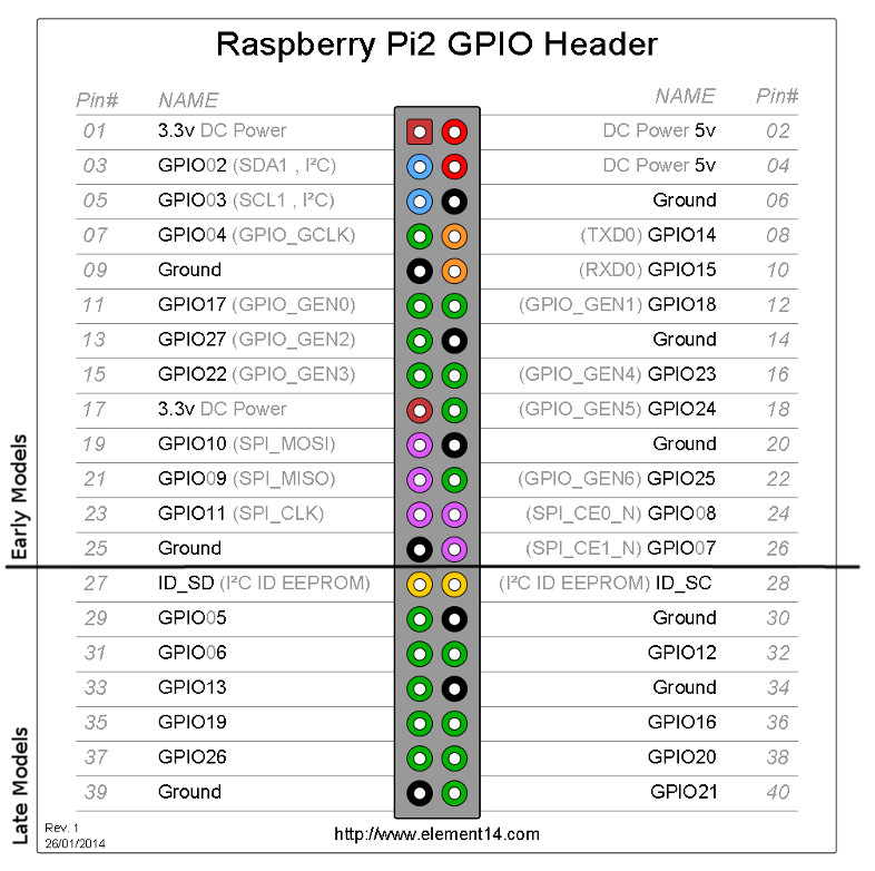
Pins:
- Red (3.3 V Power): pin 1
- Black (ground): pin 6
- Yellow (signal): pin 7; GPIO 4
#!/usr/bin/python
import RPi.GPIO as GPIO
import time, sys

flow_sensor_gpio = 4

GPIO.setmode(GPIO.BCM)
GPIO.setup(flow_sensor_gpio, GPIO.IN, pull_up_down=GPIO.PUD_UP)

global count
count = 0

def countPulse(channel):
   global count
   if start_counter == 1:
      count = count+1

GPIO.add_event_detect(flow_sensor_gpio, GPIO.FALLING, callback=countPulse)

while True:
    try:
        start_counter = 1
        time.sleep(1)
        start_counter = 0
        flow = (count / 7.5) # Pulse frequency (Hz) = 7.5Q, Q is flow rate in L/min.
        print("The flow is: %.3f Liter/min" % (flow))
        count = 0
        time.sleep(1)
    except KeyboardInterrupt:
        print('\nkeyboard interrupt!')
        GPIO.cleanup()
        sys.exit()
Temp
- https://pinout.xyz/pinout/1_wire
- https://www.amazon.com/dp/B012C597T0?psc=1&ref=ppx_yo2ov_dt_b_product_details
- https://www.circuitbasics.com/raspberry-pi-ds18b20-temperature-sensor-tutorial/
Pins:
- Red: 5V (pin 2 or pin 4)
- black: ground (8 or 14)
- Yellow: Pin 11 (GPIO 17) and Pin 12 (GPIO 18)
Not sure if we have to do the following:
sudo modprobe w1-gpiosudo modprobe w1-therm
Configuring the One-Wire interface on a Raspberry Pi, using GPIO pin 7 without a pull-up resistor.
sudo dtoverlay w1-gpio gpiopin=17 pullup=0
sudo dtoverlay w1-gpio gpiopin=18 pullup=0
sudo dtoverlay w1-gpio gpiopin=27 pullup=0
Make permanent:
sudo nano /boot/config.txtdtoverlay=w1-gpio,gpiopin=17,pullup=0 dtoverlay=w1-gpio,gpiopin=18,pullup=0 dtoverlay=w1-gpio,gpiopin=27,pullup=0- Reboot
For my system:
- GPIO 17: 28-3ce1d44312b4 Flow
- GPIO 18: 28-3ce1d4438ff7 Return
- GPIO 17: 28-3ce1d4432b6f Ambient
Verify
ls /sys/bus/w1/devicesController / Relay
Connecting the pins